Introduction
The reason I started this project is because I recently had a bad experience flying a quadcopter too far from me until I was not able to distinguish if the quad was facing me or not. It does not require much distance before a quadcopter looks like a tiny black dot in the sky. Basically, I lost orientation of the quad and I had to land way too far from my takeoff location.
I was in need of more tools (or more ways) to help myself when I will inevitably get into this situation again. The following project explains how I build a DIY solution to help a pilot know a quadcopter orientation when its far away from the point of view and easily locate the quadcopter in case of emergency landing.
Background story
I have been flying planes for many years now and over time, I learned to increase my skills and I became a nice pilot. I am still new to the RC hobby and I got pulled into flying quadcopters.
Quadcopters are not piloted the same way as planes. They look safer or easier to pilot since you can always slow down and hover if anything gets out of control.
Recently, I had an interesting experience. I was flying my quad for around 3 months and I felt too much confident: I wanted to try doing flips. Coming from a plane world, I though that climbing to a safe altitude would be the best strategy in case something went wrong.
I got carried away and I ended up to a much higher altitude and further away than I was used to. I tried to drop height and drive the quadcopter back to me but it was too late. The wind was so strong that it moved the quad further away and made the quadcopter swirl. I quickly lost orientation of the quad and had no way to bring it back.
Luckily, a more experienced pilot help me get the quadcopter back to a safe landing zone which was 615 meters away from my takeoff location.
It took me 3 hours to locate the landing site and find the quad which was still intact!
I learn multiple things this day:
- I was lacking experience and I need much more practice before attempting stupid aerobatics.
- Getting altitude for quadcopters is not as safe as for planes.
- It is always better to fly with someone more experienced than you are.
- I needed a way to know the orientation of the quad when it is over or away from me.
- A lost plane alarm buzzer would have helped me find the quadcopter much quicker.
- I was in need of a GPS module and a failsafe mode.
Project summary
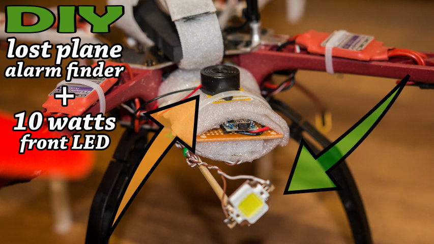
The DIY solution consist of adding two devices on the quadcopter each device for solving a specific issue.
10 watts LED
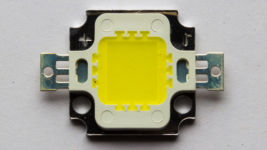
The first device is a 10 watts light-emitting diode (LED) mounted to the front of the quadcopter. This option adds to existing visual aids and help the pilot to develop his situation awareness. The front LED allows the pilot to know when the quadcopter is facing him and help the pilot recover in case of lost orientation.
This type of LED is quite bright and provides 900 to 1000 lumens of light which makes it a good candidate to be seen from far away.
As an example, here is a picture of the LED mounted to the quadcopter seen from 333 meters away.

To help locate the LED location, here is the same point of view with the LED turned off:

Note that both images are cropped version of the original image which have a much bigger field-of-view.
Lost plane alarm finder
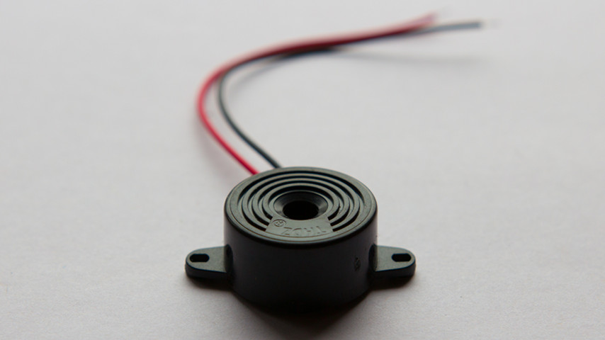
The second device is a 95 decibel (dB) piezoelectric speaker. This allows the quadcopter to be easily found in case of a crash or an emergency landing. For example, if one enter Failsafe mode, the quadcopter can land immediately (or Return To Home but that is out of scope) and there is a good chance that it will be far from your takeoff location. Tracking a beep-beep-beep sound is much more easier than estimating the landing location 1 km away.
There are already tons of existing options for a search alarm buzzer on the market, each with their own pros and cons. Some buzzer must be connected to a dedicated channel and make sound when flipping a switch on your controller. Others must be connected in series with the throttle channel and rings if the throttle signal has not changed for more than 60 seconds.
However, I prefer the DIY way since it gives more personal satisfaction and the selected option is always the preferred one for my personal needs.
With the DIY route, the piezo buzzer is much louder reaching peaks of 96 dB instead of 60-70 dB since the piezo is powered by the LiPo battery (in my case a 3S 11.1 volts) instead of a poor 5 volts. The sound volume for piezo buzzer is proportional to the voltage used to power the device meaning that a 4S LiPo battery (14.8v) would make it louder than a 3S LiPo.
Microcontroller
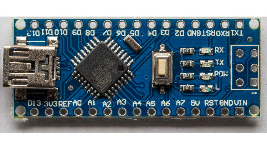
What is different about this project is that it includes an arduino nano v3, which is a microcontroller. The arduino act as the brain between the pilot and the on-board devices. It allows control of both the LED and the piezo buzzer by reading the quadcopter’s receiver signal and forwarding the pilot commands to each device.
This configuration offers much more possibilities. The most obvious is that each device is controlled by the microcontroller instead of a direct channel. This allows advanced logic to be used to implement more features.
As an example, I don’t want the LED always turned ON and certainly don’t need to have the alarm buzzing during the flight when everything is going well. So I had to come up with a way to control both devices with the transmitter.
The big innovation about this project is that both devices are controlled by the quadcopter transmitter using only a single channel.
As bonus points, with the help of the arduino, the piezo buzzer can be used as a “cellphone ringtone player” to ring the geekiest melodies…
Project data
Components and Supplies
All the hardware components required for this project are available for purchase on eBay.
Note that this project assumes that the arduino will be connected to a Remote Controlled (RC) 6-channels Receiver. This part for the project is then not listed as a ‘required’ component.
The material for this project is as follows:
| Image | Description | Qty |
|---|---|---|
|
Arduino Nano v3 | 1 |
|
|
Piezoelectric Buzzer | 1 |
|
10 Watt LEDs | 1 |
|
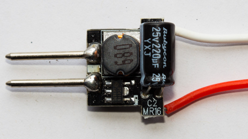
MR16 Constant Current LED Driver (12v 10w) | 1 |
|
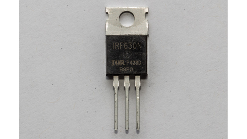
N-Channel TO-220AB Power Mosfet (IRF630N, 200V, 9.3A, 0.30-Ohm) | 2 |
|
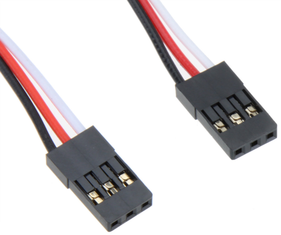
20cm Male Servo Extension Lead Wire Cable | 1 |
|
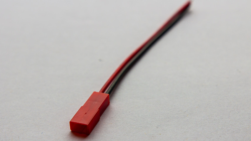
Female JST battery connector | 1 |
|
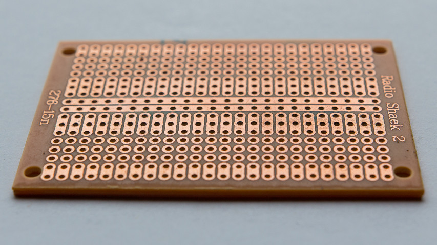
Single Side 5x7cm Prototyping Stripboard | 1 |
|
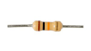
10k Ohm Resistor | 2 |

|
Wires | 1 |
|
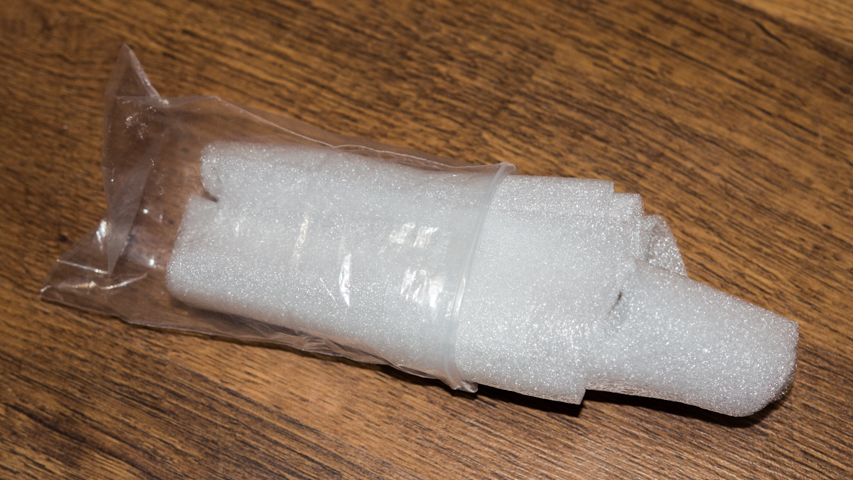
Wrapping foam | 1 |

|
Wood BBQ Skewers | 2 |
|
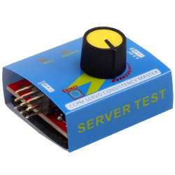
CCPM-Servo-Tester | 1 |
MR16 Constant Current LED Driver
The MR16 Constant Current LED Driver is used to drive the 10w LED. It can easily be found on eBay and light stores since the driver is used to power LED lamps which happens to use 10w LEDs.
The controller is not cheap but looks like the best logical choice. On a quadcopter, every grams counts and this driver is very light and it is the smallest form factor circuit that I could find.
I am not that much concerned about power efficiency of the driver since the project is to be mounted to a quadcopter. The small 10w LED is not significant when compared to the 4 brushless motors.
N-Channel Power Mosfet
My original design only required a single mosfet and was used as a switch to trigger the MR16 LED driver and a simple NPN Transistor (like the 2N2222A) which was also used as a switch to trigger the piezo buzzer. This setup was working fine on the arduino development board which provides 5 volts. However, once I connected the board to my 3S LiPo battery, which is 11.1 volts, the gate of the 2N2222A started leaking from collector to emitter without a signal sent to the base (in other words, the switch was always closed). The piezo buzzer started ringing without me understanding why.
Please note that your wife may get mad at you if you let the piezo buzzer ring for too long. Better use higher rated transistor!
I used the IRF630N mosfet for driving both the LED and the piezo buzzer. The mosfet is rated for much higher current and voltage (200V, 9.3A) for this scenario but it is relatively cheap and I had plenty of those at home.
Payload
I didn’t take the time to calculate the weight of each component individually. Anyway that would not be really helpful since I do not expect anyone to actually try to optimize the circuit by replacing some components by lightweight version.
The total weight of the package is 37.5 grams. This is calculated using a high precision scale and it includes everything that is required for using the controller in the field. In other words, it also includes the wrapping foam the BBQ sticks and wires.
Total cost of the project
This project is really cheap and can be completed with less than 30$.
Here is the detailed price of each items:
| Item | Link | Quantity | Total |
|---|---|---|---|
| Arduino Nano v3 | eBay | 1 | $3.17 |
| Piezoelectric Buzzer | eBay | 1 | $1.30 |
| 10 Watt LED | eBay | 1 | $1.00 |
| MR16 Constant Current LED Driver | eBay | 1 | $2.24 |
| N-Channel TO-220AB Power Mosfet | eBay | 2 | $3.521 |
| Male Servo Extension Lead Wire Cable | eBay | 1 | $1.00 |
| Female JST battery connector | eBay | 1 | $1.00 |
| Single Side 5x7cm Prototyping Stripboard | eBay | 1 | $4.562 |
| 10k Ohm Resistor | eBay | 2 | $1.003 |
| CCPM-Servo-Tester | eBay | 1 | $1.61 |
Notes:
- Bying 5 pieces is cheaper than buying 2 individual pieces.
- Lowest price is for 2 pieces.
- For a pack of 50 pieces.
Total cost: $20.40
Note that cost of usual items such as solder paste, soldering iron, multimeter and base material like wrapping foam is not included in the cost of the project.
Preparation time
The whole project can be completed in 5 to 8 hours. This is actually a rough estimated time since I did not build a second controller for another quad that I had. The estimation assumes the following:
- You already have all required components. Most of the waiting about this project comes from the fact that all components are purchased from China and takes 4-5 weeks to arrive. However, once you have all materials, the project starts to build itself at a decent pace.
- You have basic soldering skills. The duration of this project may change depending on how much you are comfortable with a soldering iron.
- You are familiar with the arduino prototyping platform. This guide will not cover how to compile the code/libraries and upload it to the arduino. There are plenty of guides and tutorials on the internet that can help you on this matter.
To make this project a reality, I had to invest much more time. Actually, from beginning to the end, it took somewhere between 50 to 80 hours. I had to learn new skills like basic electronics, designing circuits, using Fritzing software and the arduino platform but most of the time was spent on documenting and debugging the code!(there are still improvements, see below).
I decided to post this project so that others may benefit from my experience. The project can be used as a proof of concept, all issues that I encountered are already documented and the code for the project is released to the public.
Schematics
The following section shows the drawings and the schematics used by the controller.
Fritzing files
![]()
All drawings and diagrams are build using Fritzing version 0.9.2b which is an open-source hardware initiative tool that allows developers to document their prototypes and share them with others. The application already features a huge parts library but there is no support for a Generic Remote Controlled (RC) 6-Channels Receiver and for the MR16 Constant Current LED Driver.
The additional parts which are required for rendering the project are available for download:
- /MR16-Constant-Current-LED-Driver.fzpz
- Generic-2.4Ghz-RC-6ch-Receiver-OCRA.fzpz
- 3S-3600mAh-Lipo-Battery.fzpz
The project files are also available for download. Click the following link to get the Fritzing project files for this project:
Circuit Diagram
The following section shows the circuit diagram layout

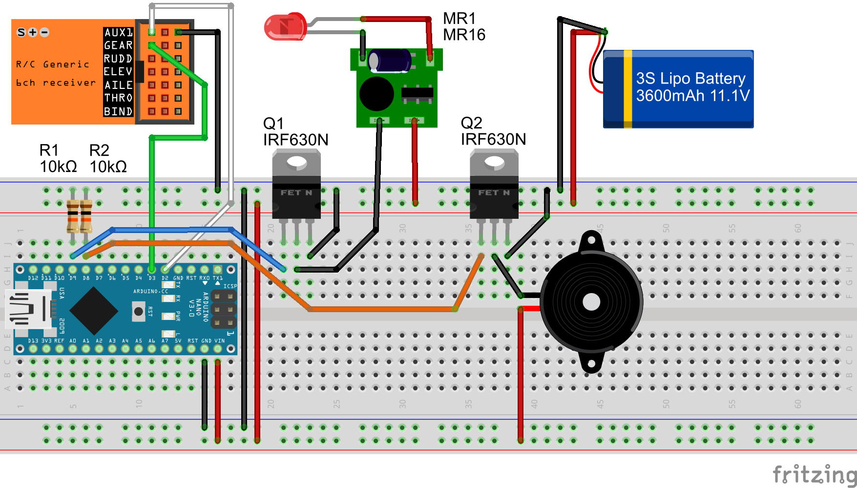
Breadboard Layout
The following section shows a breadboard layout view of the circuit.
Code
The following section defines the required libraries for compiling the main arduino sketch available below.
External libraries
The code on the arduino requires multiple external arduino libraries. The following list shows all required software libraries and their related use as part of this project:
| Name | Version | Usage |
|---|---|---|
| SoftTimers 5 | v1.1.219 | Required for all computation and handling of the LED’s ON and OFF times. |
| RcReceiverSignal 8 | v1.2.203 | Required to read PWM signals sent from the RC Receiver. |
| AnyRtttl 7 | v2.1 | Required to play RTTTL melodies data. |
| PinChangeInt | version 2402 | RcReceiverSignal library has a dependency to PinChangeInt library. |
| eRCaGuy Timer2 Counter | version 20140709 (last updated 9 July 2014) | Required to have a micros() replacement function which has a 1µs resolution instead of 4µs. |
Arduino sketch
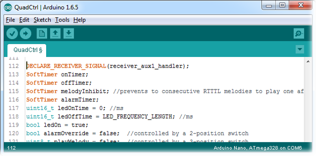
Here is the brain of the project. Source code!
Click the following to download the example below: QuadCtrl-v1.0.240.ino
//
//  QuadCtrl - Quadcopter Controller - v1.0 - 10/07/2016
//  Copyright (C) 2016 Antoine Beauchamp
//  The code & updates for the library can be found on http://end2endzone.com
//
// AUTHOR/LICENSE:
//  This library is free software; you can redistribute it and/or
//  modify it under the terms of the GNU Lesser General Public
//  License as published by the Free Software Foundation; either
//  version 3.0 of the License, or (at your option) any later version.
//
//  This library is distributed in the hope that it will be useful,
//  but WITHOUT ANY WARRANTY; without even the implied warranty of
//  MERCHANTABILITY or FITNESS FOR A PARTICULAR PURPOSE.  See the GNU
//  Lesser General Public License (LGPL-3.0) for more details.
//
//  You should have received a copy of the GNU Lesser General Public
//  License along with this library; if not, write to the Free Software
//  Foundation, Inc., 51 Franklin Street, Fifth Floor, Boston, MA  02110-1301  USA
//
// DISCLAIMER:
//  This software is furnished "as is", without technical support, and with no
//  warranty, express or implied, as to its usefulness for any purpose.
//
// PURPOSE:
//  The following code implements Buzzer & LED functionnalities to my
//  personnal quadcopter.
//
//  The buzzer is activated to play RTTTL melodies played before takeoff
//  and after landing. The buzzer is also used to play a mayday distress
//  signal that can be used to recover the quadcopter after an unexpected
//  crash.
//
//  The front-facing 10w LED is used to know the orientation of the quadcopter
//  from a far point of view. To prevent the LED from draining the battery,
//  the LED is flashing at specific rates.
//  The rates can be modulated from 40 positions varrying from always OFF
//  to always ON in a 2 second cycle. ie: a rate of 24/40 (60%) turns the
//  LED ON for 1200ms and OFF for 800ms.
//
//  Both functionalities are activated through my SPEKTRUM DX9
//  transmitter using a rotary knob, a 2-position switch and a 3-position
//  switch sending a signal to my Orange R620X DSMX2 receiver.
//
//  The receiver is connected to arduino pin 2 to read PWM signals sent
//  by the receiver.
//
//  The code is indented to run on an arduino nano v3.
//
// HISTORY:
// 10/07/2016 v1.0 - Initial release of QuadCtrl.
//
// ---------------------------------------------------------------------------


/*************************************************
 * PinChangeInt code optimizations
 *************************************************/
//http://www.benripley.com/diy/arduino/three-ways-to-read-a-pwm-signal-with-arduino/
//https://github.com/GreyGnome/PinChangeInt/wiki/Usage
//http://playground.arduino.cc/Learning/Pins
//#define NO_PIN_STATE        // to indicate that you don't need the PCintPort::pinState
#define NO_PIN_NUMBER         // to indicate that you don't need the PCintPort::arduinoPin
#define PINMODE               // defines PCintPort::pinMode which is
#define NO_PORTC_PINCHANGES   // only port D pinchanges (see: http://playground.arduino.cc/Learning/Pins)
#define NO_PORTB_PINCHANGES   // only port B pinchanges (see: http://playground.arduino.cc/Learning/Pins)

//required libraries

//Using SoftTimers v1.1.219
//Required to calculate the LED's ON and OFF times.
//Available at http://www.end2endzone.com/softtimers-a-collection-of-software-timers-to-easily-compute-elapsed-time-since-an-event-occured/
#include <SoftTimers.h>

//Using RcReceiverSignal v1.2.203
//Required to read PWM signals sent from the RC Receiver.
#include <RcReceiverSignal.h>

//Using PinChangeInt version 2402
//RcReceiverSignal library has a dependency to PinChangeInt library.
#include <PinChangeInt.h>

//Using eRCaGuy_Timer2_Counter version 20140709 (last updated 9 July 2014)
//Required to have a micros() replacement function which has a
//1us resolution instead of 4usec.
//For more information on this library, see the following:
// http://electricrcaircraftguy.com/2014/02/Timer2Counter-more-precise-Arduino-micros-function.html
// http://www.instructables.com/id/How-to-get-an-Arduino-micros-function-with-05us-pr/
#include <eRCaGuy_Timer2_Counter.h>

//Using AnyRtttl v2.1 - 06/05/2016
//Required to play RTTTL data
#include <anyrtttl.h>
#include <binrtttl.h>
#include <pitches.h>

//project's constants
#define RECEIVER_AUX1_IN_PIN 2 // we could choose any pin
#define LED_DEBUG_OUT_PIN 13
#define LED_OUT_PIN 9
#define BUZZER_OUT_PIN 8
#define LED_FREQUENCY_LENGTH 1000 //in ms
#define ANALOG_VALUE_MIN 0
#define ANALOG_VALUE_MAX 39
#define ANALOG_VALUE_THRESHOLD 3
#define DISABLE_RTTTL_PLAYBACK false

//project's switches
//#define ENABLE_SERIAL_OUTPUT

DECLARE_RECEIVER_SIGNAL(receiver_aux1_handler);
SoftTimer onTimer;
SoftTimer offTimer;
SoftTimer melodyInhibit; //prevents to consecutive RTTTL melodies to play one after the other
SoftTimer alarmTimer;
uint16_t ledOnTime = 0; //ms
uint16_t ledOffTime = LED_FREQUENCY_LENGTH; //ms
bool ledOn = true;
bool alarmOverride = false;  //controlled by a 2-position switch
uint8_t playMelody = false;  //controlled by a 3-position switch

inline int16_t clamp(const int16_t & iMin, const int16_t & iValue, const int16_t & iMax) {
  if (iValue < iMin)
    return iMin;
  if (iValue > iMax)
    return iMax;
  return iValue;
}

/*
 * Desription:
 *  Demultiplex the following from an RcReceiverSignal value:
 *  - an analog knob value (which has a resolution of 40 steps, values from 0 to 39)
 *  - a 2-position switch
 *  - a 3-position switch
 *
 *  Code sample from http://www.end2endzone.com/how-to-multiplex-rc-transmitter-switches-into-a-single-channel/#Decoding-2
 *
 *  The following mixes must be used on a Spektrum DX9 to multiplex all switches into AUX1:
 *  - RKnob > AX1,   high=-74%, low=  0%, offset=-99%
 *  - RKnob > AX1,   high=  0%, low= 54%, offset=100%
 *  - SwitchA > AX1, high=  0%, low=-69%, offset=100%
 *  - SwitchB > AX1, high=  0%, low=-46%, offset=100%
 *
 */
void demultiplexAnalog40_1x2Pos1x3Pos(const int16_t & iSignal, uint8_t & oAnalogA, bool & oSwitch2, uint8_t & oSwitch3) {
  #define setSwitches(effectiveMin,signal,effectiveMax,a,b) oAnalogA=clamp(effectiveMin,signal,effectiveMax) - (effectiveMin); oSwitch2=a; oSwitch3=b;
       if ( -150 <= iSignal && iSignal <= -105 ) { setSwitches( -147 ,iSignal, -108, 0, 0 ) }
  else if ( -104 <= iSignal && iSignal <=  -59 ) { setSwitches( -101 ,iSignal,  -62, 0, 1 ) }
  else if (  -58 <= iSignal && iSignal <=  -13 ) { setSwitches(  -55 ,iSignal,  -16, 0, 2 ) }
  else if (  -12 <= iSignal && iSignal <=   33 ) { setSwitches(   -9 ,iSignal,   30, 1, 0 ) }
  else if (   34 <= iSignal && iSignal <=   79 ) { setSwitches(   37 ,iSignal,   76, 1, 1 ) }
  else if (   80 <= iSignal && iSignal <=  125 ) { setSwitches(   83 ,iSignal,  122, 1, 2 ) }
  else
  {
    setSwitches( 0,0,0,0,0 );
  }
  #undef setSwitches
}

/*
void debugLED() {
  while (true)
  {
    digitalWrite(LED_OUT_PIN, HIGH);
    digitalWrite(LED_DEBUG_OUT_PIN, HIGH);
    delay(1000);
    digitalWrite(LED_OUT_PIN, LOW);
    digitalWrite(LED_DEBUG_OUT_PIN, LOW);
    delay(1000);
  }
}
*/

#ifdef ENABLE_SERIAL_OUTPUT
//pretty print buffer
char ppBuffer[10];

char * prettyPrint(const char * format, const uint16_t & value)
{
  sprintf(ppBuffer, format, value);
  return ppBuffer;
}
char * prettyPrint(const char * format, const int16_t & value)
{
  sprintf(ppBuffer, format, value);
  return ppBuffer;
}
#endif

/*************************************************
 * RTTTL Melodies
 *************************************************/
#define NUM_RTTTL_MELODY 14
const char simpsons[]           PROGMEM = "simpsons:d=4,o=5,b=160:c.6,e6,f#6,8a6,g.6,e6,c6,8a,8f#,8f#,8f#,2g,8p,8p,8f#,8f#,8f#,8g,a#.,8c6,8c6,8c6,c6";
const char arkanoid[]           PROGMEM = "Arkanoid:d=4,o=5,b=140:8g6,16p,16g.6,2a#6,32p,8a6,8g6,8f6,8a6,2g6";
const char cocacola[]           PROGMEM = "Coca-cola:d=4,o=5,b=125:8f#6,8f#6,8f#6,8f#6,g6,8f#6,e6,8e6,8a6,f#6,d6,2p";
const char pacman[]             PROGMEM = "pacman:d=4,o=5,b=112:32b,32p,32b6,32p,32f#6,32p,32d#6,32p,32b6,32f#6,16p,16d#6,16p,32c6,32p,32c7,32p,32g6,32p,32e6,32p,32c7,32g6,16p,16e6,16p,32b,32p,32b6,32p,32f#6,32p,32d#6,32p,32b6,32f#6,16p,16d#6,16p,32d#6,32e6,32f6,32p,32f6,32f#6,32g6,32p,32g6,32g#6,32a6,32p,32b.6";
const char mario_short[]        PROGMEM = "smb_short:d=16,o=5,b=180:e.,e.,p.,e.,p.,c.,e.,p.,g.,4p,g.4";
const char mario_death[]        PROGMEM = "smbdeath:d=4,o=5,b=90:32c6,32c6,32c6,8p,16b,16f6,16p,16f6,16f.6,16e.6,16d6,16c6,16p,16e,16p,16c";
const char mario_flagpole[]     PROGMEM = "smbflagpole:d=32,o=6,b=112:f#.4,c.5,e.5,g.5,c.,e.,8g,8e,g#.4,c.5,d#.5,g#.5,c.,d#.,8g#,8d#,a#.4,d.5,f.5,a#.5,d.,f.,8a#,b.,b.,b.,4c7";
const char mario_gameover[]     PROGMEM = "smbgameover:d=8,o=4,b=180:16c.5,16p.,16p.,16g.,p.,e.,a,b,a,g#,a#,g#,16g.,16f.,g.";
const char mario_1up[]          PROGMEM = "smb1up:d=16,o=7,b=180:e.6,g.6,e.,c.,d.,g.";
const char starwars_cantina[]   PROGMEM = "SWCantina:d=4,o=5,b=250:8a,8p,8d6,8p,8a,8p,8d6,8p,8a,8d6,8p,8a,8p,8g#,a,8a,8g#,8a,g,8f#,8g,8f#,f.,8d.,16p,p.,8a,8p,8d6,8p,8a,8p,8d6,8p,8a,8d6,8p,8a,8p,8g#,8a,8p,8g,8p,g.,8f#,8g,8p,8c6,a#,a,g";
const char tetris[]             PROGMEM = "tetris:d=4,o=5,b=160:e6,8b,8c6,8d6,16e6,16d6,8c6,8b,a,8a,8c6,e6,8d6,8c6,b,8b,8c6,d6,e6,c6,a,2a,8p,d6,8f6,a6,8g6,8f6,e6,8e6,8c6,e6,8d6,8c6,b,8b,8c6,d6,e6,c6,a,a";
const char topgun[]             PROGMEM = "TopGun:d=4,o=4,b=31:32p,16c#,16g#,16g#,32f#,32f,32f#,32f,16d#,16d#,32c#,32d#,16f,32d#,32f,16f#,32f,32c#,16f,16d#";
const char backtothefuture[]    PROGMEM = "bttf:d=4,o=5,b=100:c#4,g#.4,8c#,b.4,16a#4,16g#4,8a#.4,8g#.4,8f#4,g#.4,16g#4,16g#4,2g#.4,c#,g#.,8c#6,b.,16a#,16g#,8a#.,8g#.,8f#,1g#";
const char bond[]               PROGMEM = "bond:d=4,o=5,b=125:8e,16f#,16f#,8f#,f#,8e,8e,8e,8e,16g,16g,8g,g,8f#,8f#,8f#,8e,16f#,16f#,8f#,f#,8e,8e,8e,8e,16g,16g,8g,g,8f#,8f#,8f#,8e,16f#,16f#,8f#,f#,8e,8e,8e,8e,16g,16g,8g,g,8f#,8f,8e,8e6,2d6,8p,8b,8a,2b";

void playRtttl(uint8_t iPinNumber, const char * iBuffer) {
  //are we allowed to play another melody ?
  //is it too soon ?
  if (melodyInhibit.hasTimedOut() || melodyInhibit.getTimeOutTime()==0)
  {
    //fine play another melody

    //disable interrupts. timer2 messes up with the tone() library
    noInterrupts();
    timer2.revert_to_normal();
    interrupts();

    //play
    anyrtttl::blocking::playProgMem(iPinNumber, iBuffer);

    //enable interrupts. Configure timer2 again for 0.5us resolution.
    noInterrupts();
    timer2.setup();
    interrupts();

    //disable RTTTL playback for 100ms to allow RcReceiverSignal to
    //read the new update since the code was blocking during playback
    melodyInhibit.setTimeOutTime(500);
    melodyInhibit.reset();
  }
  else
  {
    #ifdef ENABLE_SERIAL_OUTPUT
    Serial.print(F("Too soon for playing again. Please wait "));
    Serial.print(melodyInhibit.getRemainingTime());
    Serial.print(F("ms..."));
    #endif
  }
}

uint32_t timer2GetCountWrapperFunction() {
  return timer2.get_count();
}

void setup() {
  pinMode(LED_OUT_PIN, OUTPUT);
  pinMode(LED_DEBUG_OUT_PIN, OUTPUT);
  pinMode(BUZZER_OUT_PIN, OUTPUT);

  //play booting melody
  playRtttl(BUZZER_OUT_PIN, arkanoid);

  //configure Timer2
  timer2.setup(); //this MUST be done before the other Timer2_Counter functions work; Note: since this messes up PWM outputs on pins 3 & 11, as well as
                  //interferes with the tone() library (http://arduino.cc/en/reference/tone), you can always revert Timer2 back to normal by calling
                  //timer2.unsetup()

  //configure RcReceiverSignal with an external time counter
  //eRCaGuy_Timer2_Counter lirary has 0.5us resolution.
  //The counter value must be divided by 2 to convert from 0.5us steps to 1us steps
  //which results in microseconds resolution.
  RcReceiverSignal::setExternalTimeCounter(&timer2GetCountWrapperFunction, 1, 2);

  //link RcReceiverSignal to use PinChangeInt library
  RcReceiverSignal::setAttachInterruptFunction(&PCintPort::attachInterrupt);
  RcReceiverSignal::setPinStatePointer(&PCintPort::pinState);

  // if analog input pin 0 is unconnected, random analog
  // noise will cause the call to randomSeed() to generate
  // different seed numbers each time the sketch runs.
  // randomSeed() will then shuffle the random function.
  uint16_t seed = analogRead(0);
  randomSeed(seed);

  //allow the first RTTTL melody to be played
  melodyInhibit.setTimeOutTime(0);

  //configure alarm loop count time
  alarmTimer.setTimeOutTime(50);

  #ifdef ENABLE_SERIAL_OUTPUT
    Serial.begin(115200);
    Serial.println(F("ready"));
    Serial.print(F("seed="));
    Serial.println(seed);
  #endif

  receiver_aux1_handler_setup(RECEIVER_AUX1_IN_PIN);

  onTimer.reset();
}

void processBuzzerPinUpdate()
{
  if (alarmOverride)
  {
    int count = alarmTimer.getLoopCount() % 29;
    bool pinHigh = (count ==  0 ||
                    count ==  2 ||
                    count ==  4 ||
                    count == 16 ||
                    count == 17 ||
                    count == 18 );
    if (pinHigh)
      digitalWrite(BUZZER_OUT_PIN, HIGH);
    else
      digitalWrite(BUZZER_OUT_PIN, LOW);
  }
  else if (playMelody != 0) //is 1 or 2
  {
    //debuging mode: Temporary disable RTTTL playback
    if (DISABLE_RTTTL_PLAYBACK)
      return;

    // print a random number from 0 to NUM_RTTTL_MELODY-1
    int32_t melodyIndex = random(0, NUM_RTTTL_MELODY);

    #ifdef ENABLE_SERIAL_OUTPUT
    Serial.print(F("melodyIndex="));
    Serial.println(melodyIndex);
    #endif

    switch(melodyIndex)
    {
    case 0:
      playRtttl(BUZZER_OUT_PIN, simpsons);
      break;
    case 1:
      playRtttl(BUZZER_OUT_PIN, arkanoid);
      break;
    case 2:
      playRtttl(BUZZER_OUT_PIN, cocacola);
      break;
    case 3:
      playRtttl(BUZZER_OUT_PIN, pacman);
      break;
    case 4:
      playRtttl(BUZZER_OUT_PIN, mario_short);
      break;
    case 5:
      playRtttl(BUZZER_OUT_PIN, mario_death);
      break;
    case 6:
      playRtttl(BUZZER_OUT_PIN, mario_flagpole);
      break;
    case 7:
      playRtttl(BUZZER_OUT_PIN, mario_gameover);
      break;
    case 8:
      playRtttl(BUZZER_OUT_PIN, mario_1up);
      break;
    case 9:
      playRtttl(BUZZER_OUT_PIN, starwars_cantina);
      break;
    case 10:
      playRtttl(BUZZER_OUT_PIN, tetris);
      break;
    case 11:
      playRtttl(BUZZER_OUT_PIN, topgun);
      break;
    case 12:
      playRtttl(BUZZER_OUT_PIN, backtothefuture);
      break;
    case 13:
      playRtttl(BUZZER_OUT_PIN, bond);
      break;
    default:
      #ifdef ENABLE_SERIAL_OUTPUT
      Serial.print(F("ERROR WITH RTTTL MELODY."));
      #endif
      break;
    };
  }
  else
  {
    digitalWrite(BUZZER_OUT_PIN, LOW);
  }
}

void processAux1SignalChanged()
{
  uint16_t pwnValue = receiver_aux1_handler.getPwmValue();
  RcReceiverSignal::VALUE signalValue = receiver_aux1_handler.getDeviceSignalValue(SPEKTRUM_DX9_ORANGE_R620X, pwnValue);

  uint8_t analogKnob = 0;
  demultiplexAnalog40_1x2Pos1x3Pos(signalValue, analogKnob, alarmOverride, playMelody);

  //default to always OFF
  ledOnTime = 0; //ms
  ledOffTime = LED_FREQUENCY_LENGTH; //ms

  /*
   * Note:
   *  Since the RcReceiverSignal may flicker a little (oscillate from 0 to 2),
   *  the first 3 analog values must be considered OFF. This allows the pilot
   *  to easily set the LED always OFF (without blimps).
   *
   *  Also consider last 2 analog values as always ON. This allows the pilot
   *  to easily set the LED always ON (without blimps).
   */
  if (analogKnob < ANALOG_VALUE_THRESHOLD)
  {
    //force always OFF
    analogKnob = 0;
  }
  else if (analogKnob >= ANALOG_VALUE_MAX-1)
  {
    //force always ON
    analogKnob = ANALOG_VALUE_MAX;
  }

  //map signal value to an on-time and off-time
  ledOnTime = map(analogKnob, 0, ANALOG_VALUE_MAX, 0, LED_FREQUENCY_LENGTH); //ms
  ledOffTime = LED_FREQUENCY_LENGTH - ledOnTime; //ms

  //update timers
  onTimer.setTimeOutTime(ledOnTime);
  offTimer.setTimeOutTime(ledOffTime);

  #ifdef ENABLE_SERIAL_OUTPUT
    Serial.print(F("signal="));
    Serial.print(prettyPrint("%4d", signalValue));
    Serial.print(F("% PWM="));
    Serial.print(prettyPrint("%04d", pwnValue));
    Serial.print(F(" analog="));
    Serial.print(prettyPrint("%02d", analogKnob));
    Serial.print(F(" buzzerOverride="));
    Serial.print(buzzerOverride);
    Serial.print(F(" playMelody="));
    Serial.print(playMelody);
    Serial.print(F(" ON:"));
    Serial.print(prettyPrint("%04d", ledOnTime));
    Serial.print(F(" OFF:"));
    Serial.print(prettyPrint("%04d", ledOffTime));
    Serial.println();
  #endif
}

void processLedPinUpdate()
{
  if (ledOn)
  {
    //led is ON

    //should it be turned OFF ?
    if (onTimer.hasTimedOut() && offTimer.getTimeOutTime() > 0)
    {
      //time to turn OFF the LED
      digitalWrite(LED_OUT_PIN, LOW);
      digitalWrite(LED_DEBUG_OUT_PIN, LOW);
      ledOn = !ledOn;
      offTimer.reset();
    }
  }
  else
  {
    //led is OFF

    //should it be turned ON ?
    if (offTimer.hasTimedOut() && onTimer.getTimeOutTime() > 0)
    {
      //time to turn ON the LED
      digitalWrite(LED_OUT_PIN, HIGH);
      digitalWrite(LED_DEBUG_OUT_PIN, HIGH);
      ledOn = !ledOn;
      onTimer.reset();
    }
  }
}

void loop() {
  //detect when the receiver AUX1 value has changed
  if (receiver_aux1_handler.hasChanged())
  {
    processAux1SignalChanged();
  }

  //check timers if required to toggle
  processLedPinUpdate();

  //update buzzer
  processBuzzerPinUpdate();
}
Building steps

The following section explains all the different steps on how to build my DIY quadcopter visual aids controller.
Install code on arduino
Before attempting run the given code on the arduino, you must first install the required libraries. Please follow the How to Install a Library guide available on the arduino web site.
Download links for required libraries are available in the External Libraries or References sections.
Upload the main arduino sketch to the arduino and proceed with the next step.
Setup transmitter (Tx) mixes
As explained above, this project innovation relies on the fact that both devices are controlled by the quadcopter transmitter using only a single channel. This is achieved by configuring custom mixes on the transmitter.
To know more about how mixes can be used to control more than one device with the help of a microcontroller, read the following article: How to multiplex RC Transmitter switches into a single channel.
As a reference, here are the mixes that I use for my Spektrum DX9 transmitter:
| AUX1 Mix info | Mix Output |
|---|---|
| Number | Switch |
| 0 | Right knob |
| 1 | Right knob |
| -147 | |
| 2 | H |
| 3 | G |
Note that the following mixes must match the demultiplexing code running on the arduino. If you do not use the code “as is”, then you must also adjust your transmitter mixes to reflect the change.
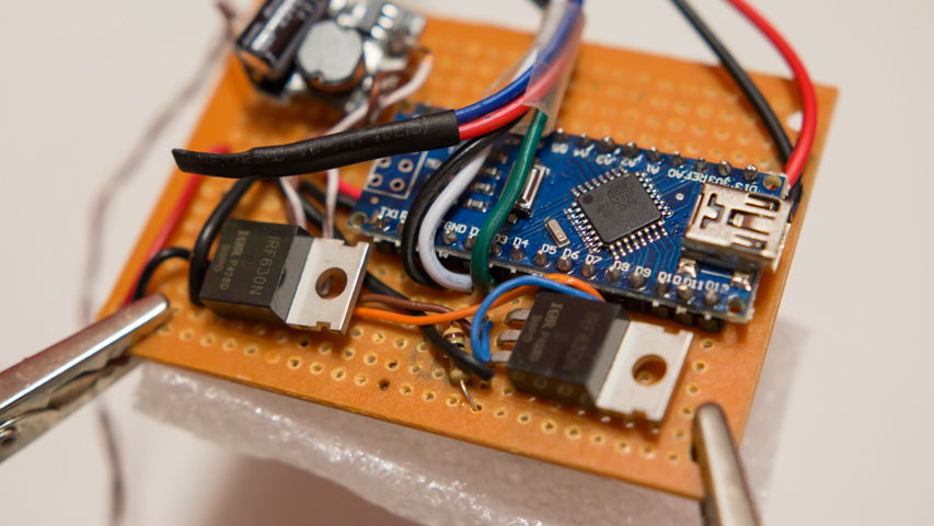
Build a prototype
The purpose of these steps is to evaluate the feasibility of the project by implementing a smaller scale of the project as a proof of concept even though that at this point you should already know that the project is viable since I already completed all steps and the controller is actually running on my personal quadcopter.
Test the code
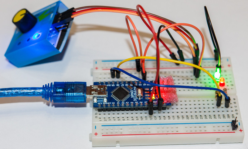
The purpose of this step is to quickly identify issue with the code as no other parts (besides the arduino itself) of the final circuit is used. Code issues are the one that should be addressed first. This step confirms that the arduino is able to read an arbitrary PWM signal and process it.
Build the circuit as showed by the picture above. For reference, the yellow and blue wires matches the blue and orange wire of the breadboard layout. These wires are connected to pins which drives low LEDs instead of high current mosfets. The prototype uses a simple CCPM Servo Tester for emulating the 6-ch receiver. In this configuration, the red LED matches the 10W front LED and the green LED matches the buzzing state.
Power the arduino using USB power. By changing the position of the CCPM Servo tester potentiometer, you should observe different behavior of each LEDs for each position of CCPM tester.
Note that since the code is already debugged, I do not expect anything to go wrong and things should be addressed easily. If you do observe issues, please verify your connections or the version used by each library dependencies.
Tx/Rx prototype integration
For a greater testing, connect your receiver and use your transmitter to change the PWM signal sent to the microcontroller.
This step verifies the quality (or precision of the signal) of the transmitter/receiver pair. It also helps validating that you configured the right mixes in your transmitter to independently control the LED and the buzzer.
Test each component (optional)
Now that you know that the code is working as expected, you may want to test each components before soldering them on the breadboard.
The final step is to integrate all real components to the breadboard prototype and use external 12v power supply (to mimic a 3S LiPo battery).
Complete the actual circuit as defined in Breadboard Layout section.
Solder components
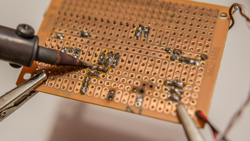
Define the position of every components on the prototyping stripboard. You should have enough room for all components and if you plan correctly, you may still have space left and be able to cut 1 or 2 cm from the sides to save additional size and weight.
Note that both mosfet do not require a heat sink. However, you may want to fold both mosfet so that the height of the total package is as low as possible so that it may fit properly inside a small cavity of the quadcopter.
Position the arduino’s USB port facing outside so that when you need to update the software, you can simply connect the package to a computer without having to disassemble or disconnect the unit from the quadcopter.
For the same reason, solder the male servo extension lead and the JST battery connector to the other side since those will require to be as close as possible to the quadcopter’s controller and battery.
Solder each component carefully following the schematics and head to the final step.
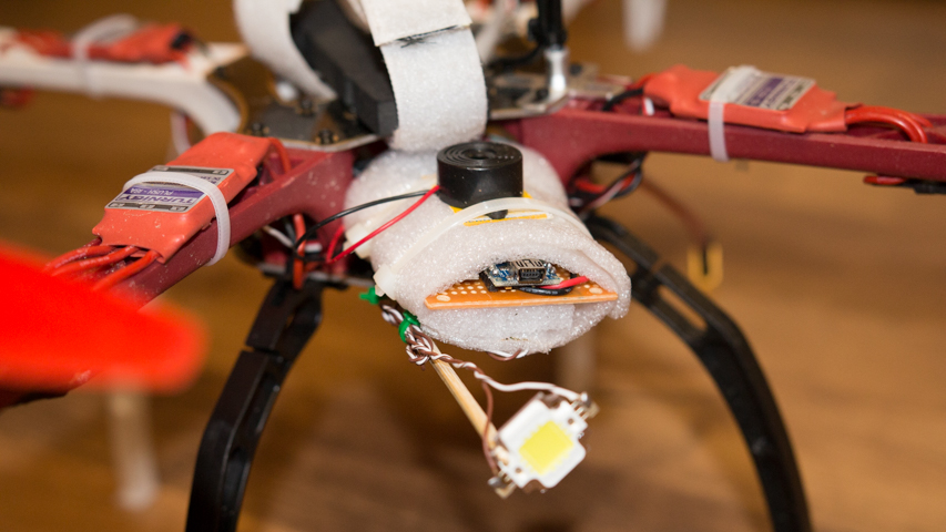
Secure the unit on the quadcopter
Once everything is ready for flight, attach the package on the quadcopter. Connect JST battery connector and each signal wire cable.
Since I was planning on removing the device for maintenance, I didn’t used glue (or anything permanent) for securing the package to the frame. Instead I used zip ties which are used for both wrapping the foam around the stripboard and attaching to the frame’s front grooves.
I also used zip ties to attach the wood BBQ skewers to the pre-drilled holes in the fuselage.
For best result, position the 10w LED below the propeller’s wind blast. This will greatly increase the lifespan of the LED since it will always be properly cooled while turned on.
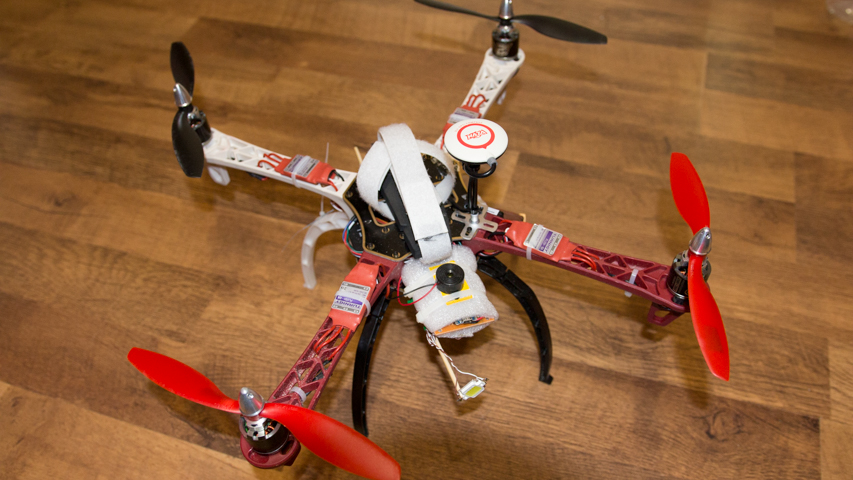
Final Result
Here is the final result:
Made anything differently?
The features of the device are fulfilling the main objectives and there is no actual need to change anything. However, there are lots of aspect of the design that could be improved. After completing this project, I though of multiple ideas that could bring the design to a higher quality level.
At the beginning of the project, I was not much concerned about weight since I was evaluating the feasibility of the project and I didn’t design the device to be something that would actually be flying. Now that it is completed, I would like to put more effort trying to reduce the total weight.
Here are most aspects that I would like to improve:
Better signal wires
Signal wires could be much improved.
First, they are way too big. The wires for the receiver signal between the 6-ch receiver (Rx) and the arduino could be made smaller. Only a small current is used to carry the signal so there is no need for not using the smallest wires available.
Second, not all wires are actually used. At the beginning of the design, I though of using the arduino to read multiple channels. In the picture above, the red and blue wires were designed to read 2 more PWM signals which would make the arduino able to decode 3 different channels. The blue and red wires are wasted grams I could save.
Finally, the length of the wires is 3-4 times longer than they actually need. When I was prototyping, it was actually convenient to have longer cable that could connect the receiver but once the unit is attached to the quadcopter, the device is almost next to the receiver and the need for longer wires is not much required anymore. The same also applies for the LED wires which had to be folded many times because they were too long.
Other LED options?
I still doubt that a single super strong LED is the way to go. In the near future, I might consider having multiple on-board middle-range LED and I am curious to see if multiple LEDs would produce more lumens than a single one. In the idea, having 2 or 3 smaller LED may make the whole thing more visible at greater distance. I may investigate other LED options which offers a better watt-to-lumens ratio.
If I ever choose to go with 2 or 3 smaller LED instead of a single super strong LED, I may also get rid of the current limiting circuit. The circuit is not particularly heavy but using smaller LED (which consumes less power), would allow me to replace the circuit by smaller/lighter resistance connected to each LED. I know that each resistance might not be super efficient (lots of heat dissipation) but it is negligible when compared to the enormous amount of energy consumed by the motors. A linear voltage regulator like the LM317 might also simplify the circuit and prevent too much heat dissipation.
Smaller form factor
Getting rid of the stripboard would also be in my plans. Now that I know the whole circuit does not required too much connections, I am now thinking of completely removing the stripboard. This would require to hot glue both the mosfets and the current limiting circuit directly to the arduino. If done properly, the amount of hot glue required should be lighter than the stripboard.
At the same time, the device would be smaller which could make it usable on other platforms like ones with a hard shell cover.
Signal (de)multiplexing nessesary?
Short answer, no.
Actually, I do not require to have an on-board arduino on the quad. There was no actual need to implement signal multiplexing and demultiplexing. To get the same functionality, I could have simply used an 8-channels receiver and the need for multiplexing/demultiplexing would be gone.
The main reason for this project was fun. ‘All work and no play makes Antoine a dull boy’. The project turned out more complicated than I first through and I had to invest a lot of my free time to code, test and to make it up to this point. Without the ‘fun’ part, this project would never went further than ideas on a sheet of paper. If I ever have to rebuild this project, the fun part would still be the first and primary goal of the project!
Modular design
For maintainability, portability and reusability reasons, it might be interesting to subdivide the device into modules (smaller reusable parts).
For instance the demultiplexor could be a perfect candidate for reusability. It could be reused on other platforms like airplanes to control non-critical flight accessories like landing lights where front, wings and tail lights could be controlled by a single channel.
The LED and buzzer could also be made into modules. Each or both could be modified to be directly connected to a dedicated channel on the receiver. If I ever upgrade the quadcopter to a 8-channels (or more) receiver, I could still use the LED and the buzzer without requiring the demultiplexor part.
References
Here is the list of all sub-articles that made this project a reality:
Documentation:
- How to multiplex RC Transmitter switches into a single channel.
- Mapping RC Transmitter PWM signal to actual transmitter values.
- Demystifying RC Transmitter Mixing.
- RC Transmitter Mix Calculator.
Arduino libraries:
- SoftTimers – A collection of software timers to easily compute elapsed time since an event occurred.
- libRtttl – A c++ library (with UI) for compressing/optimizing the RTTTL audio format.
- AnyRtttl – A feature rich arduino library for playing RTTTL melodies.
- RcReceiverSignal: an arduino library for retrieving the RC Transmitter value from an RC Receiver pulse.
Notes
none


Comments